Modification B) Hardwired BF0 / BF1 Pins for different Bus / Core ratio
Now - given you did not manage to get one of the rare Pentium Overdrive 180 / 200 chips you could speed up the processor board quite a bit. What have we here ? A processor board offering 3.3V DC supply and a 60 MHz base clock. Why not installing -say- a Pentium 120 at least, or a 166 or even a Pentium 200 ?
Should fit in and run. Data sheet says "3.3 Volt Core Voltage" - Okay, we got that here.
Well now ... on Clone Boards you will find some jumpers that switch the base clock from 50 to 60 and to 66 MHz - and you will find some jumpers that alter the "Bus / Core" ratio - usually 2 pairs of 3-pin jumpers along with a wicked list of possible settings for all Pentiums from 75 to 200 MHz internally.
Not so on our P90 Platform.
The two 3-pin jumpers you can find are for totally different purposes and do not alter anything frequency or core-ratio related. Sad fact is: the two pins on the processor socket, which are intended to set the core / bus ratio are left open. Connected to nothing.
But the bad luck on the one side is good luck on the other. You can tie the two pins to whatever you need - either +3.3 Volt or GND. Even better: left open the processor itself pulls the pins up to +3.3 V.
And leaving both BF0 and BF1 open sets them in a logical "1" status ... which is 2:3 bus / core ratio. Not accidently, if you think of the 60 MHz board clock and the 90 MHz core clock. A ratio of 2:3 - or 1:1.5 is exactly the ratio of 60:90 MHz. (Lot fun with basic calculations we had, eh ? Not much anymore after elementary school ...)
Okay - so where are the two darned pins anyway ? See the picture below.
BF0 is the 8th pin left in the 5th row from above - sits just over the "5" in "R157".
BF1 is the 8th pin left in the 4th row from above - sits just under the "1" in "C168".
(or 45° right / up from BF0 ...)
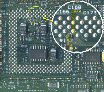
Position of the BF0 / BF1 pins on the Pentium socket
Next you need is a list of the possible combinations, which can be achieved with the various number of processors. You should keep in mind that we only have 60 MHz base clock available. If you use a processor designed for 50 MHz this may work for some time - but maybe fail pretty soon. All processors designed for 66 MHz base clock can be used - but will run at 60 MHz with a lower internal clock rate. I'll give the resulting values in a separate column.
| Pentium P54C "Classical" Type Core / Bus Settings |
| Type | | Clock | Ratio | | BF0 | BF1 | | @ 60 MHz | DC Power |
| P-75 | | 50 MHz | 2:3 (1.5x) | | 1 | 1 | | n.a. | 2.65 A |
| P-90 | | 60 MHz | 2:3 (1.5x) | | 1 | 1 | | 90 | 2.95 A |
| P-100 (a) | | 50 MHz | 1:2 (2.0x) | | 0 | 1 | | n.a. | 3.25 A |
| P-100 (b) | | 66 MHz | 2:3 (1.5x) | | 1 | 1 | | 90 | 3.25 A |
| P-120 | | 60 MHz | 1:2 (2.0x) | | 0 | 1 | | 120 | 3.73 A |
| P-133 | | 66 MHz | 1:2 (2.0x) | | 0 | 1 | | 120 | 3.40 A |
| P-150 | | 60 MHz | 2:5 (2.5x) | | 0 | 0 | | 150 | 3.85 A |
| P-166 | | 66 MHz | 2:5 (2.5x) | | 0 | 0 | | 150 | 4.25 A |
| P-200 | | 66 MHz | 1:3 (3.0x) | | 1 | 0 | | 180 | 4.60 A |
"0" = tied to GND, "1" = left open
DC Power lists the total current drawn on the 3.3 Volt supply lines |
Here's an example on how to "hardwire" a Pentium 166 processor onto the P90 Platform. The P-166 uses a 2:5 bus / core ratio - according to the list above this requires both pins at "0" = GND. You simply solder one wire from the BF0 pin to the unmarked end of capacitor C162 and another wire from BF1 to the unmarked end of capacitor C210. You could as well drill the ends together and tie them both to any of the two capacitors - or solder a single wire from GND to BF0 and further to BF1 ... whatever you prefer.
It is only important that you do not connect other pins than the two BF-pins.
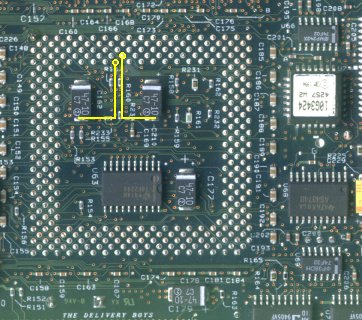
Wiring BF0 and BF1 to GND for 2:5 bus / core ratio
After the modification, after installing the P-166 CPU and starting up the operating system you may run a speed check tool (like that included in QCONFIG coming with IBM PC-DOS after 6.1). It will determine the processor speed at about 150 MHz - which is what you'd awaited, when you multiply 60 MHz with a 2.5x factor.
Please keep in mind what is said in the "cooling chapter": you will need a good heatsink and you better upgrade the 3.3 Volt Regulator heatsink according to Jim Shorneys recommendation and examples given on his own "P90 Complex Page".
The power drawn from a P-166 is 4.25 Amps at 3.3 V at 66 MHz and 166 MHz internally. One might suppose that it behaves like a real P-150 processor when "underclocking" it with 60 MHz input to 150 MHz internally. But that will result in a 3.85 Amp power draw at 3.3 Volt. This is 0.9 Amps more than the original P-90 processor, which takes 2.95 Amps @ 3.3 Volt.
For the 3.3 Volt regulator an increase of 0.9 Amps is roughly an increase of about 1.5 Watts of additional thermal load, which has to be dissipated by the heatsink. Therefore good cooling and the heatsink upgrade is not luxury - it is essential.
Back up to the Top
|