The importance of cooling certain components
It is a commonly known phenomenia that flow of electricity causes heating up components. What we want on our electric heatings might become a problem in the "silicone world".
With using your fingers hovering over some chips you will find that some of them grow pretty hot during operation. Some of the components - namely the voltage regulators and the processor itself - have heatsinks already to spread the generated heat into the surrounding air. Some components don't have heatsinks but appear pretty hot already.
As a "rule of thumb" (not only figuratively) you can do the following test: wetten your finger a bit and touch the surface of a component. If the water evaporates immediately it is above 75 degrees Celsius - and most likely too hot to touch anyway with the bare fingers. Any temperature below 60°C is not just "nice to touch" but you can stand it for at least several seconds. If you are capable to keep your finger on that particular part for much longer (or: very long time) it will surely be below 50°C.
Not a qualified testing method - and your individual mileage may vary - but a good quick-test to find out excessive heaters.
As it goes for the silicon chips: the most of them are designed to operate reliable up to about 115°C at the chip core which may result in about 75 - 85°C Case Temperature. Also a common rule here is: the colder - the better.
Every "chip tuner" should be aware of the fact that the attempt to speed up the board functions will cause more heat. So it is not enough to rise the clock-frequency and alter the pinout a bit ... and hope that the technical reserves of the basic design will allow reliable operation as usual.
Not true.
If you speed up the board clock and if you switch to a higher-performance processor this will have an influence on the heat generation. The least you can await is a higher power drawn by the processor in the first place along with higher power drawn by the accompanying chips as well - which results in a higher load on the voltage regulator at least. Which then results in more heat emission of that part - as well as higher heat emission on the processor itself compared with the one it substituted.
There you have the first two places already where you need to do something, where you have to optimize the cooling.
A good reference on how to modify the heatsink for the LT-1084 3.3 Volt main regulator on the P-90 platform can be found on Jim Shorneys "P90 Complex Page". Jim has done some major research on that topic and offers some very good and easy to do modifications there.
Since I am known as one who dislikes to "invent the wheel" any day again I want to thank Jim for his excellent work and only reference to his page from here. Thanks Jim.
For the processor there are several good cooling kits available. The P-90 case is fairly common and still in use for the latest AMD and even Intel processors that use Socket-7 or Socket 370 or Super-7. The fixing clips might not fit optimal however - the Socket-5 used a narrower clip than the later ones or a sort of "Wire Spring" clip. You need to be a bit inventive and creative here to keep the heatsink on the processor - which sits on the board facing down.
So just laying it on the processor will not work anyway. You need a tight fit and some pressure between heatsink and processor case.
 Older processors like the P-90 to P-150 mainly use an all-ceramic case with a relatively large and flat surface. In terms of heat distribution this case is however sub-optimal, because ceramic material keeps the heat inside for longer (low heat transient / dissipation factor). Older processors like the P-90 to P-150 mainly use an all-ceramic case with a relatively large and flat surface. In terms of heat distribution this case is however sub-optimal, because ceramic material keeps the heat inside for longer (low heat transient / dissipation factor).
 Later versions had a ceramic case with a metal (mainly golden) plate inlayed - the so-called "heat spreader". Unfortunately the heat-spreader and the case are not of the same height, so that the case itself cannot be used to distribute heat. The area of the heat spreader is about a half of that of the entire upper case surface only. In fact the heat spreader covers the "processor die" only. Later versions had a ceramic case with a metal (mainly golden) plate inlayed - the so-called "heat spreader". Unfortunately the heat-spreader and the case are not of the same height, so that the case itself cannot be used to distribute heat. The area of the heat spreader is about a half of that of the entire upper case surface only. In fact the heat spreader covers the "processor die" only.
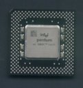 Things came even worser with the introduction of the Pentium MMX, where Intel started using a plastic case with a thicker, but smaller heat spreader. Some of the "classical" (Non-MMX processors) inherited this case as well - like for example the P-166 and the P-200 of the later series. Things came even worser with the introduction of the Pentium MMX, where Intel started using a plastic case with a thicker, but smaller heat spreader. Some of the "classical" (Non-MMX processors) inherited this case as well - like for example the P-166 and the P-200 of the later series.
You are facing two problems here:
- the active area that is capable to disribute the heat from the processor to the heatsink is rather small
- there is a potential danger to mount the heatsink tilted ....
The other components of the P90 platform get medium warm at least. The 82497 cache controller could be used with those cooling kits designed for the Pentium 90 which uses side hooks - it has the exact identical physical size.
A "Socket-7" cooling kit which uses a clip over the heatsink cannot be used. The 82497 socket lacks the catches typically for Socket-7 where these clips hook behind.
Problem childs are the 82492 cache RAMs. 10 of them are located on both sides of the complex card. Fortunately they are physically located one against the other on both sides, so you could try to get 10 smaller heatsinks (like the one used on earlier revisions of the XGA-2 card RAMDAC) and build yourself 5 pieces of a "C" shaped metal bracket. Since you need to use thermal conductive grease between heatsink and cache chip and while this stuff is rather sticky you will surely manage to affix the two adjacent heatsinks and bring your self-made clip over the two between the heatsink fins. The clip must apply some stronger mechanical pressure onto the two heatsinks to press them together and onto the chips.
Unfortunately I haven't managed to get appropriate heatsinks in the required amount so far. The heatsinks used on old 4 Mbit Token Ring adapters might be used - but they have side guides that needed to be milled down at least, or there is a potential (or: likely) risk that these guides touch the cache chip outer pinrows.
And BANG ... Apocalypse.
Back up to the Top
|